Tuesday, September 16, 2008

LiFePO4 40138 Cell - Close Up

I admit it. I have to take things apart. A device sitting there hermetically sealed in shrinkwrap seems normal at first. At some point, however, a small voice starts to taunt from somewhere inside that shrinkwrap. And that's it. Out comes the tools.

Here's a closer look at a single 40138 cell. This construction seems to be fairly typical of other 40138 cells.
Before: Cell with insulating end label and shrink wrap in place. The cell ends are covered with an adhesive label. There's an 'X' cut into each label that falls over the cell vent. There's a vent in each end of the cell. The rest of the cell is covered in a layer of shrink wrap plastic.

After: The complete cell in all its bare aluminum glory. The body of the cell (tubing and end caps) is aluminum.
Close-up of cell end showing thick cast end cap with gas vent and four depressions. Each end has a vent and four circular depressions. The depressions appear to be features of the end caps, which appear to be cast. The depressions are 1.47mm deep and the vent is 1.59mm deep.
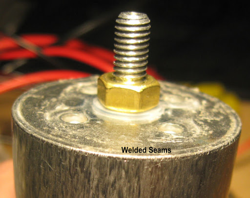
End caps are welded to the cell body tube. The joints between the body tubing and end caps are welded.


I don't mind working with a bare cell on the bench, but it's important to ensure the cell covering remains intact in use. The cell can be shorted between positive and negative terminals like any other cell, but it can also be shorted between either terminal and the outer cell casing (aluminum body tube and end caps).

For example - this cell is fresh from the charger and is reading 3.557 volts between the positive and negative terminals. There is 1.074V between the positive terminal and the case, and 2.482V between the negative terminal and the case.

Whether you're making an electric bicycle pack or a battery for your electric trolling motor, mount the cells securely and isolate them from each other and any part of the battery pack that will conduct electricity. It won't take very many miles of e-biking to wear thru the shrink wrap.

Saturday, September 6, 2008

Working with 40138 Cells

40138, A123Systems 18650 and 26650 LiFePO4 Cells Here's a 'family portrait' of sorts. The pair of yellow cells are A123Systems 18650 cells. These were removed from a Black and Decker VPX pack. The larger white cell is a 26650 cell from A123Systems. It was removed from a 36volt DeWalt DC9360 battery pack. The green cell is our text subject, a 40138 LiFePO4 cell.

The numbers - 18650, 26650 and 40138 - give cell dimensions in milimetres. The first pair of numbers - 18, 26, and 40 are the cell diameter. The 650 and 138 are cell length without terminals...almost. The smaller cells swap the zero around. The pair of cells from A123Systems are about 65mm long - not 650.

The smaller cells have connections spot welded on. The larger cell is fitted with 6mm bolts. This makes it easy to wire a pack, and change pack configuration later.

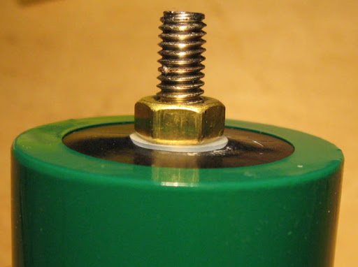
Closeup of 40138 negative terminal showing nut and sealing washer

Here's a close-up of a cell terminal. See the nylon washer under the nut? That's part of the cell's sealing system. The nuts on the terminal studs must stay in place. Loosen the nut and the cell will leak.

The cell is covered with a layer of shrink wrap insulation. There's a barcode label on the aluminum cell casing in addition to the one on the outside.

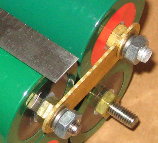
Cell connection example - connecting strap with nut and lockwasherHere's a terminal mounting example. The connection strap is against the nut installed on the cell. There's an optional flat washer against the strap, then a mandatory lock washer, and nut.

Connecting example using 1/4 inch ring terminals

Here's another wiring example. The 1/4 inch crimp-on ring terminals are connected to 10AWG wires. There's enough room for a pair of terminals as long as they're 'back to back'.

It's very important to secure each connection. Use lock washers, spring washers, locktite, or something similar on all cell connections. Electrical resistance increases when a connection becomes loose. Just like an electric stove burner, current flow and resistance equals heat. At best, performance will decrease as nuts loosen. At worst, the connection can heat enough at higher electrical flow to start a fire.

Inspect cell connections as part of your preventive maintenance schedule. You can use fingernail polish on the end of the nut to see if the connection has loosened.

It's best to use a torque wrench when assembling cells into a pack. Maximum torque is 6.9 lb-in or .78 nm.

Monday, August 25, 2008

The Boss Escapes!

More fun! We continued discharges in 5A increments are got up through 7C with a constant 70A discharge. The test cell gave up 9.4Ah in a hair over eight minutes before reaching the 2.1V cutoff. Cell temperature peaked at 52.6ºC (126.7ºF).

Here's a recap of 55A thru 70A:

55A thru 70A / 5.5 to 7C


While we were talking about the way the capacity slowly creeps downward with each increase in load, we heard familiar whining noises from the bosses office. We decided we had to get to a 10C discharge so we could stop delivering food to his office three times a day. Besides - he needs a shower...

The cell isn't rated for a continuous 10C discharge so we took advantage of the option on the 10X CBA amplifier to cycle amplifier power during a test. We cycled power/load in roughly 15 second intervals. First two 'spikes' are 15 seconds load, 15 seconds 'rest'. Then we walked it out to 30 seconds on, 15 off; then 45 seconds on and 30 seconds off. The test ran for nine minutes 50 seconds and the CBA reported a cell capacity of 16.4Ah.

100A / 10C pulse discharge

Now..about the bosses office - Febreze or Lysol? Both!

Saturday, August 16, 2008

More Power!


Here are the results from the last three discharge cycles on our test cell. This takes us to a 55A load. As you can see from the charts posted so far, power delivery and voltage drop is consistent and predictable.

We've varied charge between a single 2A charger up to 5x chargers for a 10A initial charge rate. The only difference was charge time.

One nice feature of the 500W CBA amplifier is that we can turn the amplifier off and on during a test. This will allow us to simulate 'pulse and glide' power delivery and show voltage recovery during the 'glide' times. It will also allow us to discharge a cell to 2.1V at higher rates without overheating the cell.

End of test cell temperature is staring to come up. We've gotten to 47ºC at the end of the 55A test. Cooling starts immediately once the load comes off and contunes to ambient - even when the warm cell is connected to a 10A charge.

Stay tuned while we decide if a 10C (100A) pulse is enough to get the boss out of the office...

Tuesday, August 12, 2008

Throttle Almost Half Way Open

It's been an interesting couple of days! The West Mountain CBA Amplifier arrived and it started to absorb electrons almost immediately after we ripped the box open. We started the higher rate discharges at 1C (10A) primarily because we've changed the test configuration from earlier tests.

The basic CBAII is fed by a pair of 12AWG silicone leads connected to the cell via Anderson Powerpole connectors. The amplifier requires connecting the cells to its 5/16 inch terminal bolts. We decided to wire the cell to the amplifier with 10AWG wires - two per pole - with crimp-on ring terminals. It's giving us very low resistance connections and should give us an open highway for electrons to flow from the test cell.

(Click the image for a readable chart.)


The first round of tests took us from 10A thru 40A (4C) in 5A steps. This chart covers discharge cycles 23 thru 31. 25 and 28 were aborted due to improper setup of the monitoring software. (The boss forgot to enable the amplifier at test start. He's exiled to his office until we test at 10C.)

Test environment is a 24º-25ºC (about 77ºF) air conditioned lab. A couple of the tests were conducted on a quick-turn from the chargers - we didn't let the cell sit to cool and stabilize. Starting cell temperature ranged from 25º to 27ºC. End of discharge temperatures from 20A to 40A ranged from 34º to 42ºC (93º to 108ºF). We're finally starting to see a bit of heat on discharge. There's no significant heating on a 10A charge (1º-2ºC above ambient) - same for discharge up to 15A. Max discharge heating noted so far is 17ºC.

Capacity is trending slightly lower as discharge rate increases. We're down to 9.91Ah at the 40A rate. We've noticed a slight variation in the cutoff setting for the Voltphreak 2A chargers and we expect this will intruduce some cell capacity variation. Overall, though, we're happy with the consistency of the data so far.

Stay tuned for the next installment - maybe we'll hit 10C and let the boss out of the office.

Saturday, August 9, 2008

The End of the Break-In?

Break-in testing continues. We're up thru cycle 22 with the basic CBAII and it appears that cell capacity has stabilized. Capacity varies a bit with discharge rate. 5A discharge produces 10.36Ah. 20A provides a bit between 10.08 to 10.13 Ah. A 25A continues discharge provides 10.19 Ah.

Comparing 10A loads, we've gone from 9.63Ah at cycle 1 to 10.26 at cycle 16 for a 6.5% gain in capacity. The experienced cell provides more consistent power until end of charge as well.

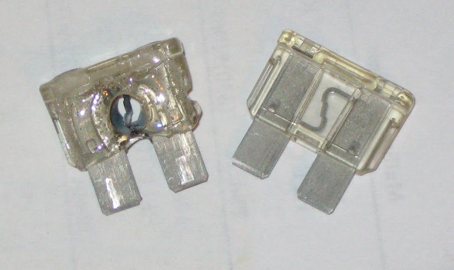
This is the end of our break-in tests for now. We've also reached the end of our discharge tests with our current CBAII configuration - 25A is the upper limit for a single cell. 26A does interesting things to fuses ...


Discharge cycle 23 at 10A is the first cycle with West Mountain Radio's 500W add-on amplifier for the CBAII. We'll increase the load 5A each cycle and see how these cells perform at higher rates. The cells are rated at up to 10C (100A) peak discharge.

Testing to date has been limited by equipment. Let's see how these cells perform when we open the throttle!

Wednesday, July 30, 2008

Break-in thru Cycle 14

Break-in tests continue. Here's a summary of discharge cycles 1 thru 14 as reported by the CBA:


You can click the picture for a larger (readable!) image. The last part of the test number is the discharge cycle from new.