Monday, December 22, 2008

Torque and Assembly Blocks

We have a couple of updates for you. The first is a 'demonstration' of why torque matters when attaching hardware to 40138 terminals. The second is one way to connect cells into a road-ready battery.

As the manufacturer of all 40138 cells currently on the market, Phoenix Silicon International (PSI) 'gets' to tell us how best to use our cells. One point they make clear is that it's not good to overtighten the nuts when wiring cells. Yes - here comes the 'why not?' part!

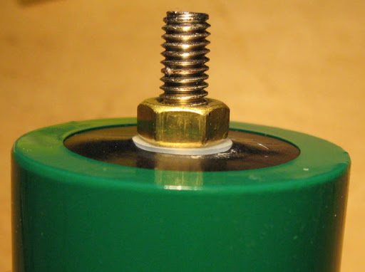
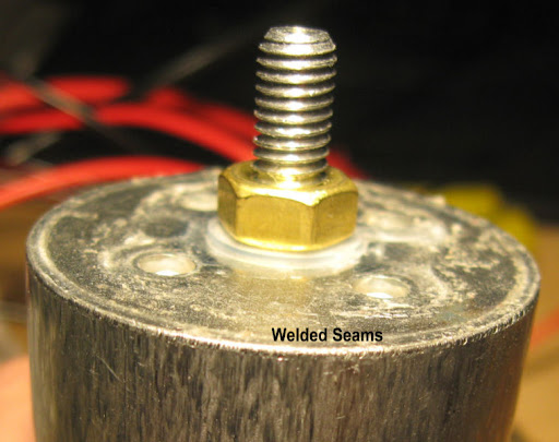
The terminal studs are made of different metals. The negative pole is plated copper. The positive - and the subject of our demonstration - is aluminum. And it's hollow. And it's threaded inside and out.

PSI gives us a torque limit of 6.9 in/lb or .78 nm and highly recommends using a torque driver or small torque wrench when installing hardware.


There are a number of decent (and better than decent!) torque drivers on the market and one can spend $157 and more - like this from SK. We found a fully functional yet frugal torque driver at Harbor Freight (online item 65397) for $34.99.


It's easy to set, 7 in/lb is far enough off the bottom of the scale to be reasonably accurate, and it just plain works. The driver accepts standard hex screwdriver bits, so you'll either need a specialty 10mm nutdriver bit or an adaptor for your 1/4 inch drive socket. Either way, it's cheap, easy, quick, brainless, and won't destroy the cells.

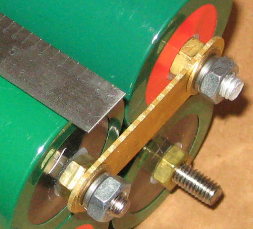
Ok - so you want to do more than string a bunch of cells together and make your living room lamp glow. Now what? Remember from an earlier post that the plastic seals on the cells are not designed to be pothole, expansion joint, or rock-hopping proof. A leaking cell is not a happy cell. We need a way to hold the cell bodies securely in the battery case so that the cells aren't hanging by the wiring - then we can hit the road.

PSI has one solution - the molded plastic assembly block.


Fit and finish of these is excellent! The mold part lines are accurate and there's no flash. The blocks have 'T' shaped locking tabs on two sides and can be assembled into many shapes. They don't have permanent locks - they're a friction fit - so the pack can be reconfigured easily.


Here's a pretty boring 12S pack. The block has .6 inch deep extensions cable-side to protect the wiring from the sides of the battery box. The extensions have pre-molded locations for fastening the pack into a hard box.

The blocks fit tightly enough that one can handle the pack, twist it around, and suspend it by one block and everything stays locked together.

One feature designed into the blocks is the gap between cells. This allows the center cells in larger packs to get cooling air. This isn't an issue for these cells until you start pulling 60+ amps from a cell, but it's one less thing to have to worry about when filling a box for a plug-in hybrid or pure EV.

For more information or to order assembly blocks or connecting straps, visit us at www.rechargeablelithiumpower.com

Monday, November 3, 2008

Lithium VS Lead

Is a picture worth a thousand words?

In this corner, weighing in at 24 lbs, is a 36V 12Ah pack of AGM lead acid. And in this corner, weighing in at 10 lbs, is a 36V 10Ah pack of LiFePO4.


The LiFePO4 pack consists of 12 40138 cells in series. The lead acid pack is three Werker 12V 12Ah batteries from Batteries Plus. In each pack, cells were fully charged and balanced. They were both discharged thru a 10A load until reaching the pack cut-off of 30V for the lead and 29V for the LiFePO4. Ambient temperature was 21°C.


The lead acid pack started just above 36V but voltage started to drop early on and kept falling until hitting a 'shoulder' at around 6.6Ah. The LiFePO4 pack started above 36V and stayed until 8.4Ah.

Voltage Support: Advantage Lithium.

The 12Ah lead pack provided just under 7Ah (58% of rated capacity), while the 10Ah LiFePO4 pack provided just over 9.6Ah (96% of rated capacity).

Power output: Advantage Lithium.

Discharge cycles: Lead acid should give somewhere between 300 and 500 cycles at 100% depth of discharge. Our LiFePO4 should give about 1500 cycles at 100% depth of discharge.

Discharge cycles: Advantage Lithium

Weight: 10lbs VS 24lbs Advantage Lithium

Overall value: Lead was $44.95 each for a total of $134.85. If we get 400 cycles of 6.93Ah, we're paying $.0486 per Ah. (A more realistic 300 cycles costs us $.0649 per Ah.) LiFePO4 at $48 each was $576. If we get 1500 cycles of 9.63Ah, we're paying $.0399 per Ah.

Overall value: Advantage Lithium

Smaller, lighter, more power for a longer period, no hazardous chemicals - what's not to like?!

Saturday, November 1, 2008

LiFePO4 Battery Pack Management - Part 1

Welcome Back!

You just know that any day that starts with a good cup of coffee and new toys to play with is heading in the right direction! We’ve had a couple of these days in a row – here’s how they’ve unfolded so far:

The first part of the fun began when UPS brought the battery management board kit that we ordered from Gary Goodrum at TPPacks.com. He and others on the Endless Sphere battery forum designed a battery management board tailored to PSI and A123 LiFePO4 cells used in electric bicycle-sized battery packs.

It took a couple of minutes to remember which box the soldering irons were in, then the fun started. The BMS went together quickly and worked first time. Always a good sign!


The next piece of the puzzle happened along last week when our friends at UPS brought us a couple of boxes. Now we have a new batch of 40138 cells to use – and some new battery chargers to test.


Stay tuned for part two - the fun is just getting started!

Thursday, October 2, 2008

Energy Plans and Our Future

Welcome to October!

The tests continue on our guinea pig cells. We've completed 50 discharge cycles on 'old silver'. It's in the middle of a slow discharge test with periodic internal resistance samples - 30 minutes down, 4 1/2 hours to go. We'll post internal resistance results for our most experienced cell once we've worked thru the numbers.

We've also gotten requests for a look at the equipment we're using to perform these tests. Thank you for the requests - your reviews are on their way!

We'd like to depart from tech for a couple of minutes and talk about one of the reasons we're interested in LiFePO4 cells and their support. Thanks for your indulgence as we editorialize a bit.

We've just finished watching a couple of clips from C-SPAN. The latest is a short discussion of the connectedness of energy, food, and water in both the global and US economy. Here's a link to the main C-SPAN energy page. Scroll down to the 'Recent Programs' area and look for the "Clinton Global Initiative Conference" from September 25th. This talk, moderated by Tom Brokaw, was a conversation with Bob Zoellick, President of the World Bank, Shimon Peres, President of Israel, T. Boone Pickens, Chairman & CEO of BP Capital Management, Helle Thorning-Schmidt, leader of the Danish Social Democratic Party, and Gavin Newsom, Mayor of San Francisco.

One point we came away from was the reminder that it's very difficult or impossible in a complex and interconnected system to solve only one problem at a time. It's sort of like medical triage in a way. Basic first aid reminds us to scan the area for immediate threats first, then move quickly to check airway, breathing, and circulation. We can get to broken bones a bit later.

If an accident victim is found unconscious, not breathing, and bleeding from an artery, we have to work on controlling the bleeding and do something about getting oxygen into the system in short order. Focus on either problem while ignoring the other virtually ensures 'mission failure'.

Put another way - if you find yourself in a hole, the first step is to stop digging.

As we prepare this, our representatives in Washington DC are working on the "Emergency Economic Stabilization Act of 2008". One of the numbers we hear is that it will cost the US Government at least 700 billion dollars to stabilize things and restore confidence in the economy, credit system and stock market.

$700 billion is an interesting number and one we've heard before - from Texas oilman Boone Pickens. He reminds us in his advertisements and on the Pickens Plan website that we're spending around $700 billion each year for foreign oil. This money leaves the country and doesn't provide jobs or tax income.

We must have an energy plan in this country that helps us transition to renewable energy and helps us wean ourselves - the quicker the better - from petroleum imports. We think groups such as Pickens' and the WE campaign are helping bring energy awareness into the US presidential campaign. We think it's all connected - energy, food supply, water, the economy, jobs, climate change, transportation - and that the ability to solve these challenges is ours. We've proven in our past that with a plan and desire we can climb great heights.

There's discussion by some that we need a "Manhattan Project" of sorts for energy and the economy. Tom Brokaw referenced the '100,000 garages' concept attributed to author Tom Friedman while talking with Mayor Newsom in the interview referenced in paragraph four. I found that the reference is from Friedman's book Hot, Flat, and Crowded. Here's a quote from WIRED magazine:

"Twelve guys and gals going off to Los Alamos won't solve this problem...We need 100,000 people in 100,000 garages trying 100,000 things — in the hope that five of them break through."
So...here we are, typing and listening to the battery analyzer's cooling fan cycle on and off as our test cell is poked and prodded. Which of you, of the interconnected 'us', will be one of Friedman's five to find solutions? What part, if any, will LiFePO4 play in our renewable future?

Enough of this for now - back in the garage!

Tuesday, September 16, 2008

LiFePO4 40138 Cell - Close Up

I admit it. I have to take things apart. A device sitting there hermetically sealed in shrinkwrap seems normal at first. At some point, however, a small voice starts to taunt from somewhere inside that shrinkwrap. And that's it. Out comes the tools.

Here's a closer look at a single 40138 cell. This construction seems to be fairly typical of other 40138 cells.

Before: Cell with insulating end label and shrink wrap in place. The cell ends are covered with an adhesive label. There's an 'X' cut into each label that falls over the cell vent. There's a vent in each end of the cell. The rest of the cell is covered in a layer of shrink wrap plastic.

After: The complete cell in all its bare aluminum glory. The body of the cell (tubing and end caps) is aluminum.
Close-up of cell end showing thick cast end cap with gas vent and four depressions. Each end has a vent and four circular depressions. The depressions appear to be features of the end caps, which appear to be cast. The depressions are 1.47mm deep and the vent is 1.59mm deep.

End caps are welded to the cell body tube. The joints between the body tubing and end caps are welded.


I don't mind working with a bare cell on the bench, but it's important to ensure the cell covering remains intact in use. The cell can be shorted between positive and negative terminals like any other cell, but it can also be shorted between either terminal and the outer cell casing (aluminum body tube and end caps).

For example - this cell is fresh from the charger and is reading 3.557 volts between the positive and negative terminals. There is 1.074V between the positive terminal and the case, and 2.482V between the negative terminal and the case.

Whether you're making an electric bicycle pack or a battery for your electric trolling motor, mount the cells securely and isolate them from each other and any part of the battery pack that will conduct electricity. It won't take very many miles of e-biking to wear thru the shrink wrap.

Saturday, September 6, 2008

Working with 40138 Cells

40138, A123Systems 18650 and 26650 LiFePO4 Cells Here's a 'family portrait' of sorts. The pair of yellow cells are A123Systems 18650 cells. These were removed from a Black and Decker VPX pack. The larger white cell is a 26650 cell from A123Systems. It was removed from a 36volt DeWalt DC9360 battery pack. The green cell is our text subject, a 40138 LiFePO4 cell.

The numbers - 18650, 26650 and 40138 - give cell dimensions in milimetres. The first pair of numbers - 18, 26, and 40 are the cell diameter. The 650 and 138 are cell length without terminals...almost. The smaller cells swap the zero around. The pair of cells from A123Systems are about 65mm long - not 650.

The smaller cells have connections spot welded on. The larger cell is fitted with 6mm bolts. This makes it easy to wire a pack, and change pack configuration later.

Closeup of 40138 negative terminal showing nut and sealing washer

Here's a close-up of a cell terminal. See the nylon washer under the nut? That's part of the cell's sealing system. The nuts on the terminal studs must stay in place. Loosen the nut and the cell will leak.

The cell is covered with a layer of shrink wrap insulation. There's a barcode label on the aluminum cell casing in addition to the one on the outside.

Cell connection example - connecting strap with nut and lockwasherHere's a terminal mounting example. The connection strap is against the nut installed on the cell. There's an optional flat washer against the strap, then a mandatory lock washer, and nut.

Connecting example using 1/4 inch ring terminals

Here's another wiring example. The 1/4 inch crimp-on ring terminals are connected to 10AWG wires. There's enough room for a pair of terminals as long as they're 'back to back'.

It's very important to secure each connection. Use lock washers, spring washers, locktite, or something similar on all cell connections. Electrical resistance increases when a connection becomes loose. Just like an electric stove burner, current flow and resistance equals heat. At best, performance will decrease as nuts loosen. At worst, the connection can heat enough at higher electrical flow to start a fire.

Inspect cell connections as part of your preventive maintenance schedule. You can use fingernail polish on the end of the nut to see if the connection has loosened.

It's best to use a torque wrench when assembling cells into a pack. Maximum torque is 6.9 lb-in or .78 nm.

Monday, August 25, 2008

The Boss Escapes!

More fun! We continued discharges in 5A increments are got up through 7C with a constant 70A discharge. The test cell gave up 9.4Ah in a hair over eight minutes before reaching the 2.1V cutoff. Cell temperature peaked at 52.6ºC (126.7ºF).

Here's a recap of 55A thru 70A:

55A thru 70A / 5.5 to 7C


While we were talking about the way the capacity slowly creeps downward with each increase in load, we heard familiar whining noises from the bosses office. We decided we had to get to a 10C discharge so we could stop delivering food to his office three times a day. Besides - he needs a shower...

The cell isn't rated for a continuous 10C discharge so we took advantage of the option on the 10X CBA amplifier to cycle amplifier power during a test. We cycled power/load in roughly 15 second intervals. First two 'spikes' are 15 seconds load, 15 seconds 'rest'. Then we walked it out to 30 seconds on, 15 off; then 45 seconds on and 30 seconds off. The test ran for nine minutes 50 seconds and the CBA reported a cell capacity of 16.4Ah.

100A / 10C pulse discharge

Now..about the bosses office - Febreze or Lysol? Both!

Saturday, August 16, 2008

More Power!


Here are the results from the last three discharge cycles on our test cell. This takes us to a 55A load. As you can see from the charts posted so far, power delivery and voltage drop is consistent and predictable.

We've varied charge between a single 2A charger up to 5x chargers for a 10A initial charge rate. The only difference was charge time.

One nice feature of the 500W CBA amplifier is that we can turn the amplifier off and on during a test. This will allow us to simulate 'pulse and glide' power delivery and show voltage recovery during the 'glide' times. It will also allow us to discharge a cell to 2.1V at higher rates without overheating the cell.

End of test cell temperature is staring to come up. We've gotten to 47ºC at the end of the 55A test. Cooling starts immediately once the load comes off and contunes to ambient - even when the warm cell is connected to a 10A charge.

Stay tuned while we decide if a 10C (100A) pulse is enough to get the boss out of the office...

Tuesday, August 12, 2008

Throttle Almost Half Way Open

It's been an interesting couple of days! The West Mountain CBA Amplifier arrived and it started to absorb electrons almost immediately after we ripped the box open. We started the higher rate discharges at 1C (10A) primarily because we've changed the test configuration from earlier tests.

The basic CBAII is fed by a pair of 12AWG silicone leads connected to the cell via Anderson Powerpole connectors. The amplifier requires connecting the cells to its 5/16 inch terminal bolts. We decided to wire the cell to the amplifier with 10AWG wires - two per pole - with crimp-on ring terminals. It's giving us very low resistance connections and should give us an open highway for electrons to flow from the test cell.

(Click the image for a readable chart.)


The first round of tests took us from 10A thru 40A (4C) in 5A steps. This chart covers discharge cycles 23 thru 31. 25 and 28 were aborted due to improper setup of the monitoring software. (The boss forgot to enable the amplifier at test start. He's exiled to his office until we test at 10C.)

Test environment is a 24º-25ºC (about 77ºF) air conditioned lab. A couple of the tests were conducted on a quick-turn from the chargers - we didn't let the cell sit to cool and stabilize. Starting cell temperature ranged from 25º to 27ºC. End of discharge temperatures from 20A to 40A ranged from 34º to 42ºC (93º to 108ºF). We're finally starting to see a bit of heat on discharge. There's no significant heating on a 10A charge (1º-2ºC above ambient) - same for discharge up to 15A. Max discharge heating noted so far is 17ºC.

Capacity is trending slightly lower as discharge rate increases. We're down to 9.91Ah at the 40A rate. We've noticed a slight variation in the cutoff setting for the Voltphreak 2A chargers and we expect this will intruduce some cell capacity variation. Overall, though, we're happy with the consistency of the data so far.

Stay tuned for the next installment - maybe we'll hit 10C and let the boss out of the office.

Saturday, August 9, 2008

The End of the Break-In?

Break-in testing continues. We're up thru cycle 22 with the basic CBAII and it appears that cell capacity has stabilized. Capacity varies a bit with discharge rate. 5A discharge produces 10.36Ah. 20A provides a bit between 10.08 to 10.13 Ah. A 25A continues discharge provides 10.19 Ah.

Comparing 10A loads, we've gone from 9.63Ah at cycle 1 to 10.26 at cycle 16 for a 6.5% gain in capacity. The experienced cell provides more consistent power until end of charge as well.

This is the end of our break-in tests for now. We've also reached the end of our discharge tests with our current CBAII configuration - 25A is the upper limit for a single cell. 26A does interesting things to fuses ...


Discharge cycle 23 at 10A is the first cycle with West Mountain Radio's 500W add-on amplifier for the CBAII. We'll increase the load 5A each cycle and see how these cells perform at higher rates. The cells are rated at up to 10C (100A) peak discharge.

Testing to date has been limited by equipment. Let's see how these cells perform when we open the throttle!

Wednesday, July 30, 2008

Break-in thru Cycle 14

Break-in tests continue. Here's a summary of discharge cycles 1 thru 14 as reported by the CBA:


You can click the picture for a larger (readable!) image. The last part of the test number is the discharge cycle from new.

Sunday, July 27, 2008

Cell Break-In?

I've read in a couple of papers that lithium iron phosphate (LiFePO4) calls have a break-in period. I decided to pull a cell out of stock and see how break-in might look.

The cell I tested is a cylindrical 40138 cell. It's 40 mm (1.6 in) in diameter and 138 mm (5.4 in) long. Nominal voltage is 3.2 and nominal capacity is 10Ah. These cells can handle up to a 100A surge.

I used a West Mountain Radio CBAII for the discharge load and data logging. I recharged each cell with at least one Voltphreaks single cell charger. Ambient temperature was 75 to 77 degrees F. Low voltage cutoff was set to 2.1V. The cell was loaded with 10A for the early tests, though later tests included 20A and 25A.

Here are the numbers:
  1. 9.63
  2. 9.76
  3. 9.91
  4. 9.92
  5. 9.91
  6. 10.01
  7. 9.89
  8. 10.10
  9. 10.21
  10. 10.10 (20A discharge)
  11. 10.21 (20A discharge)
  12. 10.05 (25A discharge)
  13. 10.04 (25A discharge)

I'll run a few more cycles at 10A to see if nine cycles is a reasonable break-in period or if there's more capacity available.

For more information:

West Mountain Radio CBAII (http://www.westmountainradio.com/)

Voltphreaks single cell charger (voltphreaks.com)

Let the Fun Begin!

Welcome!

This is a log of experiments with Lithium Iron Phosphate (LiFePO4) batteries. We'll do some lab testing, track industry progress and research, and check-in with people putting their batteries to work.

Enjoy!